INTRODUCTION
Positron Emission Tomography (PET) is a radiotracer imaging technique based on the administration (typically by injection) of compounds labelled with positron emitting radionuclides to a patient under study. When the radio-isotope decays, it emits a positron, which travels a short distance before annihilating with an electron. This annihilation produces two high-energy (511 keV) gamma photons propagating in nearly opposite directions, along an imaginary line called Line of Response (LOR).
In PET imaging, the photons emitted by the decaying isotope are detected with gamma cameras. These cameras consist of a lead collimator to ensure that all detected photons are propagated along parallel paths, a crystal scintillator to convert high-energy photons to visible light, photo-multiplier tubes (PMT) to transform light signals into electric signals, and associated electronics to determine the position of each incident photon from the light distribution in the crystal (Ollinger & Fessler, 1997).
We have researched on how Artificial Neural Networks (henceforth ANNs or NNs) could be used for bias-corrected position estimation. Small-scale ANNs like the ones considered in this work can be easily implemented in hardware, due to their highly paral-lelizable structure. Therefore, we have tried to take advantage of the capabilities of ANNs for modelling the real detector response.
BACKGROUND
Traditionally, Anger logic (Anger, 1958) has been the most popular technique to obtain the the position of the centroid, or centre of the light distribution inside the scintillator crystal by means of a simple formula. The solution proposed by Anger involves connecting the PMT outputs to a simple resistor division circuit to obtain only four signals (X_, X+, Y_, Y+). However, Anger logic introduces some important drawbacks in the detection process: non-uniform spatial behaviour, differences between each PMT gain or the deformation of the light distribution when it approaches the edge of the scintillator. These problems are alleviated by using correction maps.
However, the presence of all these phenomena in traditional detectors still reduces the intrinsic resolution and produces non-uniform compression artifacts in the image and the so called border effects. The main consequence is an unavoidable reduction of the Useful Field Of View (UFOV) of the PET camera, which usually covers up to 60% of each crystal dimension.
With other methods such as Statistics Based Positioning (SBP) or Maximum Likelihood (ML) positioning, this UFOV can be increased to approximately the 80% of each dimension of the crystal, but these methods involve a heavier computational cost (Joung, Miyaoka, Kohlmyer & Lewellen 2001) (Chung, Choi, Song, Jung, Cho, Choe, Lee, Kim & Kim, 2004).
These drawbacks have not been fully overcome yet. Therefore, our proposal to introduce ANNs in the detection process as good quality estimators is well-grounded.
Some previous research has been made in this area for PMT (A.M. Bronstein, M.M. Bronstein, Zibulevsky & Zeevi, 2003) and Avalanche Photodiode (APD) based (Bruyndockx, Leonard, Tavernier, Lemaitre & Devroede, 2004) detectors using neural networks. In this work, the detectors are based on continuous scintillators and Multi-Anode PMTs (MA-PMTs) employing charge division read-out circuits (Siegel, Silverman, Shao & Cherry, 1996).
ANN APPROACH TO 2D POSITIONING IN PET
Materials and Methods
We have employed the GEANT4 (Agostinelli, 2002) simulation toolkit to model the detector and to generate realistic inputs for the NN. The electronic read-out of the resistor circuit was performed with SPICE analysis. The supervised training and validation of theANNs have been carried out with the MATLAB Neural Networks
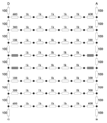
Figure 1. Siegel’s DPC diagram
Toolbox (The Mathworks, Inc., 2004). We have chosen the RPROP algorithm (Riedmiller & Braun, 1993) because it proved to converge faster than the standard gradient descent algorithm and other variants such as the Levenberg-Marquardt algorithm. Radial basis (RB) networks were also considered but were discarded in the end due to their inferior performance.
Detector Characteristics
The model of the detector under study comprises a 49 x 49 x 10 mm3 continuous slab of LSO scintillator crystal coupled to a Hamamatsu H8500 Flat-Panel MA-PMT. The read-out electronics is a conventional DPC-like resistive charge division circuit that proves to model Anger’s logic accurately. Taking the resistor network pattern used byAliaga et al. (Aliaga, Martinez, Gadea, Sebastia, Benlloch, Sanchez, Pavon & Lerche, 2006) as a starting point, we have designed a new resistor network based on the architecture proposed by S. Siegel (Siegel, Silverman, Shao & Cherry, 1996) (Fig. 1) that allows us to estimate the 2D positioning with better results. As in the previous design, all 64 channels (one per anode of the H8500) are coded into only 4 output lines, which are then fed into current sensitive preamplifiers. The current-ratio matrices A, B, C and D corresponding to each output were obtained from electronic read-out using SPICE analysis. The network was analyzed applying the superposition theorem for electric circuits.
Neural Networks
Given a collimated source S of g photons with origin at (x, y, z) emitting perpendicularly to the detector surface, we can describe the interaction of a photon in the detector as a random variable X ^ A , being, A a vector of elements a, the number of photoelectrons arriving at each anode of the MA-PMT. Thus, the elements of the vector J are the inputs of the NN, which can be written as
where J is the kth output of the charge division network, G the vector of pad gains of the MA-PMT (in our case randomly distributed between 1 and 3) and R., the transfer function of the DPC from the ith anode to the kth output of the resistors network.
The Universal Approximation Theorem (Haykin, 1999) claims that any continuous function, defined over a determined region, can be approximated uniformly, with arbitrary precision, by a Multi-Layer Perceptron (MLP) of two hidden layers. Then, our position estimator can be expressed as
being W’and b the weights and biases of each neuron of the NN. In order to adapt the NN estimator to a function f, we begin from a training set composed of pairs (J,, X) where X. = (x, y) is the position of the source and J. = fX) is a realization of the outputs of the charge division network for an interaction with origin at position Xi. Thus, the weights and biases of the NN are modified following a gradient descent algorithm (backpropagation) to minimize the mean squared error
where F is the transfer function of the NN. Initial values of weights and biases are usually determined following the Nguyen-Widrow rule (Nguyen & Widrow, 1990).
Optimization
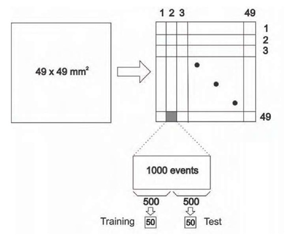
The detector surface was partitioned in 49×49 positions of 1 mm2 each. An amount of 1000 valid events were generated on each position using GEANT4. Of these 1000 events, 500 were used to compose training subsets and the remaining 500 to compose test subsets, as depicted in Figure 2.
For each network architecture, 20 different trainings were averaged, each one with different initial weights and arbitrary gains for each anode. The number of epochs was fixed to 800 to ensure convergence in all cases. We preferred not to use cross-validation as there was no scarcity of patterns to train the network. The chosen activation function was the hyperbolic tangent (tanh).
We reduced our study to MLPs of two hidden layers. A third layer would only increase complexity without showing any significant improvement. Our analysis showed that an increment on the number of neurons in the second hidden layer improves the linearity of the response, reducing the systematic error, while an increase in the number of neurons in the first hidden layer improves the spatial resolution.
There are two different approaches for 2D positioning: a single NN with 4 inputs and 2 outputs, or two independent NNs for 1D positioning on each axis. For the first scheme, we have simulated MLPs with two hidden layers and up to 25 hidden neurons (considering N1 + N2 < 25, and N1 > N2, where N1 is the number of neurons in the first hidden layer and N2 is the number of neurons in the second one. Thus, the NN architectures are represented as: number of inputs/N1/N2/number of outputs) to prevent overtraining.
Figure 2. Methodology to obtain the training/test subsets
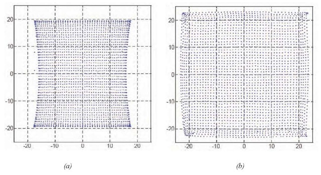
Figure 3. 2D positioning histogram for (a) centroid (Anger) based estimator and (b) NN estimator, using a 49×49 grid with 1 mm spacing
Results
The optimum network architecture found using a single MLP was 4/15/8/2. However, the best results were achieved with the double MLP estimator, with a 4/9/6/1 architecture, reaching a mean systematic error below 0.4 mm at almost all the detector FOV.
In Fig. 3, we can observe a 2D positioning histogram for a grid of 49×49 points separated 1 mm both using a centroid estimator (a) and a NN estimator (b).
The figure clearly shows that the centroid approach introduces non-uniform compression artifacts in the borders of the crystal, while the NN estimator successfully corrects these artifacts and produces a more uniform FOV in both dimensions. This improvement is quite significative as the UFOV increases from de 30^30 mm2 to 40×40 mm2, which means approximately a 90% of the MA-PMT effective area for normal incidence (Mateo, Aliaga, Martinez, Monzo & Gadea, 2007).
FUTURE TRENDS
It would be desirable to develop a method to extend this approach to Depth Of Interaction (DOI) estimation, especially to deal with oblique incidence. With this objective, additional work is being carried out by our group (Lerche, Benlloch, Sanchez, Pavon, Gime-nez, Fernandez, Gimenez, Escat, Cerda, Martinez &. Sebastia, 2005). This would add a fifth input, Z, to the ANN, which would enable a very accurate and fully 3D reconstruction of the interaction point within the scintillator.
It would also be interesting to implement the ANN training on a hardware platform, to perform fast on-site trainings to and to enable us to calibrate the PET instrumentation automatically.
And last, but not least, we are working on a high precision testbench (Fig. 4), which has recently been presented in the Real Time Conference 2007 (Monzo, Aliaga, Herrero, Martinez, Mateo, Sebastia, Mora, Benlloch & Pavon, 2007), allows to link several simulation tools for each part of the PET system, enabling us to model the effects of the electronics in each part of the design separately. In this setup, there are separate analog and digital parts. The analog part is composed by an Application Specific Integrated Circuit (ASIC), and it includes an implementation of our DPC. The digital part consists of a Field Programmable GateArray (FPGA) board, where the neural network is going to be embedded, among other elements related to signal processing. In addition to that, we intend to install a radioactive source to obtain real stimuli instead of our current synthetic data.
Figure 4. Block diagram of the high precision testbench under development
CONCLUSION
ANNs have proved to be good position estimators for PET, and an interesting alternative to traditional Anger logic. The benefits of using ANN-based position estimators include lower systematic errors, and also lower standard deviations of the systematic error, increased UFOV (up to 90% of the MA-PMT effective area, for normal incidence), less compression artifacts on the crystal borders and slightly better spatial resolution, especially on the borders.
Regarding the DPC circuit, it allowed a reduction of complexity both in terms of number of variables and in terms of hardware resources.
KEY TERMS
Anger Logic: A classic procedure to obtain the position of incidence of a photon on the scintillator crystal, which requires connecting the photomultiplier outputs to a resistive network to obtain only four outputs. With these signals, the position of the scintillation centroid is easily obtained using a simple formula. This method is acceptable in the central area of the crystal but it introduces a considerable error near its borders.
Depth Of Interaction (DOI): Depth inside the scintillator crystal where a photon interacts and produces a light distribution. Its 2D coordinates coincide with those of the incidence point for normal incidence but they differ slightly for oblique incidence. Therefore, its determination is vital for oblique incidence cases.
Discretized Positioning Circuit (DPC): An analog resistive network that receives a large amount of currents and “codes” them into a reduced number of them, introducing a minimum delay. These new currents are linear combinations of those generated by the photodetectors.
Gamma Camera: A camera that detects gamma rays (often called Anger camera).
Multi-Layer Perceptron (MLP): A kind of feedforward neural network which has at least one hidden layer of neurons.
Neural Network: A network of many simple processors (“units” or “neurons”) that imitates a biological neural network. The units are connected by unidirectional communication channels, which carry numeric data. Neural networks can be trained to find nonlinear relationships in data, and are used in applications such as robotics, speech recognition, signal processing or medical diagnosis.
Photomultiplier Tube (PMT): A part of the PET detector that receives the electromagnetic energy from the scintillator cristal and transforms that energy into electric pulses. This conversion is done in two stages: firstly the photons are absorbed, producing free electrons, and secondly a cascade amplification takes place.
Positron Emission Tomography (PET): PET is a nuclear imaging technique based on the administration of radioactive substances (radiotracers), whose molecules have a radioactive isotope (radionuclide), to a patient under study, with the aim to trace some chemical or physiological process that takes place in the body, typically for diagnosis of heart diseases, cancer, etc. The images obtained in a PET system are 2D sections of the concentration distribution of a radiotracer inside the body. When joining these sections, a medical 3D image can be obtained.
Scintillator Crystal: When a particle interacts inside a scintillator cristal, it deposits energy. The scintitillator crystal re-emits part of that energy as photons in the visible spectrum. To allow this light to be measured from the outside, the crystal must also be transparent to that light. This is done by doping the crystal so that permitted states are created in the forbidden band of the material.
Useful Field of View (UFOV): Area of the scintil-lator crystal surface on which the incidence of gamma rays produces reasonable estimations of the position of incidence.


